2.6 Image Buttons — Buzzer Control
Use images as clickable buttons to turn the onboard buzzer on and off.
Overview
LVGL images can become interactive by adding the LV_OBJ_FLAG_CLICKABLE flag. This example uses two image icons — a buzzer symbol and a mute symbol — as buttons that control the buzzer on GPIO 45.
What You’ll Learn
Making image objects clickable (an alternative to
lv_imgbtn)Controlling a passive buzzer with PWM via
ledcWriteTone()Using C-array images for button icons
Before You Begin
Complete the setup steps in Preparation before continuing.
Note
Use the recommended Arduino IDE settings in Recommended Board Settings unless this lesson says otherwise.
Open the example sketch from the code package:
LAFVIN-ESP32-S3-Multimedia-Kit-main/2.LVGL/06_LVGL_IMG_BTN/06_LVGL_IMG_BTN.ino
Signal |
ESP32-S3 |
|---|---|
BUZZER |
GPIO 45 |
Upload and Test
Connect the board with a USB Type-C data cable.
Open
06_LVGL_IMG_BTN.inoin Arduino IDE.In the Tools menu, select
ESP32S3 Dev Moduleas the board and choose the correct serial port.Click Upload.
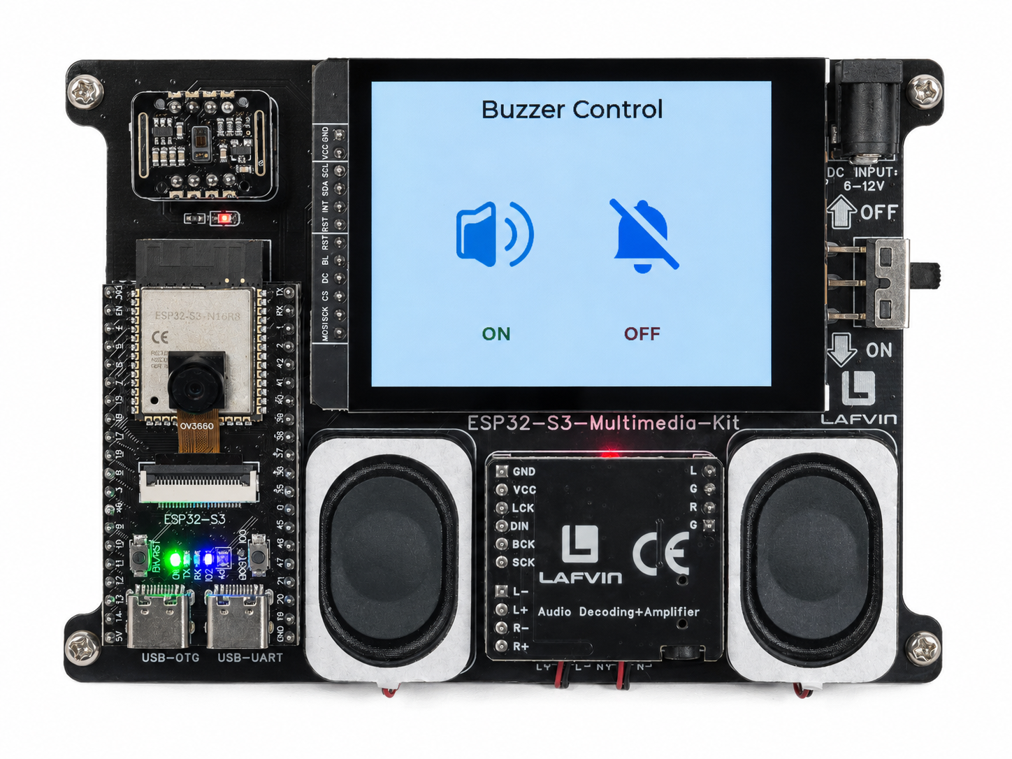
The screen shows two large image buttons:
Left: a buzzer/speaker icon with a green “ON” label
Right: a mute icon with a red “OFF” label
Tap the buzzer icon — you should hear a continuous tone from the onboard buzzer. Tap the mute icon to stop it.
How the Code Works
The buzzer control logic is implemented in 06_LVGL_IMG_BTN.ino.
Image Buttons
Two image objects — a buzzer icon and a mute icon — are created from C-array image data (similar to 2.5 Embedded Image Display). Each is made clickable with LV_OBJ_FLAG_CLICKABLE and assigned an event callback.
img_btn_buzzer = lv_img_create(lv_scr_act());
lv_img_set_src(img_btn_buzzer, &buzzer);
lv_obj_align(img_btn_buzzer, LV_ALIGN_CENTER, -60, 0);
lv_obj_add_flag(img_btn_buzzer, LV_OBJ_FLAG_CLICKABLE);
lv_obj_add_event_cb(img_btn_buzzer, buzzer_btn_event_handler, LV_EVENT_CLICKED, NULL);

img_btn_mute = lv_img_create(lv_scr_act());
lv_img_set_src(img_btn_mute, &mute);
lv_obj_align(img_btn_mute, LV_ALIGN_CENTER, 60, 0);
lv_obj_add_flag(img_btn_mute, LV_OBJ_FLAG_CLICKABLE);
lv_obj_add_event_cb(img_btn_mute, mute_btn_event_handler, LV_EVENT_CLICKED, NULL);
Buzzer Control
A single setBuzzer() helper handles both active and passive buzzer types. Active buzzers are driven with digitalWrite(); passive buzzers use ledcWriteTone() to generate a 2 kHz square wave.
void setBuzzer(bool state) {
  buzzer_on = state;

  if(ACTIVE_BUZZER) {
    digitalWrite(BUZZER_PIN, state ? HIGH : LOW);
  } else {
    if(state) {
      ledcWriteTone(BUZZER_PIN, BUZZER_FREQ);
    } else {
      ledcWriteTone(BUZZER_PIN, 0);
    }
  }
}

static void buzzer_btn_event_handler(lv_event_t * e) {
  if(lv_event_get_code(e) == LV_EVENT_CLICKED) {
    setBuzzer(true);
  }
}

static void mute_btn_event_handler(lv_event_t * e) {
  if(lv_event_get_code(e) == LV_EVENT_CLICKED) {
    setBuzzer(false);
  }
}
PWM Setup
During setup(), the buzzer pin is configured based on the type selected by the ACTIVE_BUZZER compile-time flag. A passive buzzer is attached to a PWM channel with 8-bit resolution.
if(ACTIVE_BUZZER) {
  pinMode(BUZZER_PIN, OUTPUT);
  digitalWrite(BUZZER_PIN, LOW);
} else {
  ledcAttach(BUZZER_PIN, BUZZER_FREQ, BUZZER_RESOLUTION);
  ledcWriteTone(BUZZER_PIN, 0);
}
In the provided sketch:
ACTIVE_BUZZERis set tofalseby default — change it totruefor self-oscillating buzzersThe buzzer button is offset 60 px left of centre and the mute button 60 px right
ON/OFFlabels are placed below each button in green / red respectively
Try This Next
Change
2000inledcWriteTone()to a different frequency (e.g., 1000 or 4000)Try switching to active buzzer mode by defining
ACTIVE_BUZZERAdd more image buttons with different tones (low / medium / high)